 Shubham Iyer
Drivetrain Torsional Test Stand
Our drivetrain yokes are machined from 7075 aluminum, and until now the only number we had for how much torque they can take came out of FEA. I'm leading a team of four designing a stand that loads the propshaft yoke and the front inboard and outboard yokes in torsion until they fail. The point is to put a measured failure torque next to the simulated one.
What I did
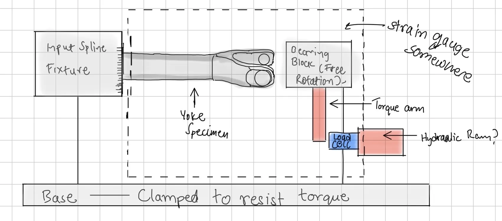
I sized the stand for up to 400 lb-ft. The first version loads the yoke through a lever arm, and we left room to swap in a hydraulic cylinder later. For measurement I picked S-beam load cells, strain rosettes and a DAQ.
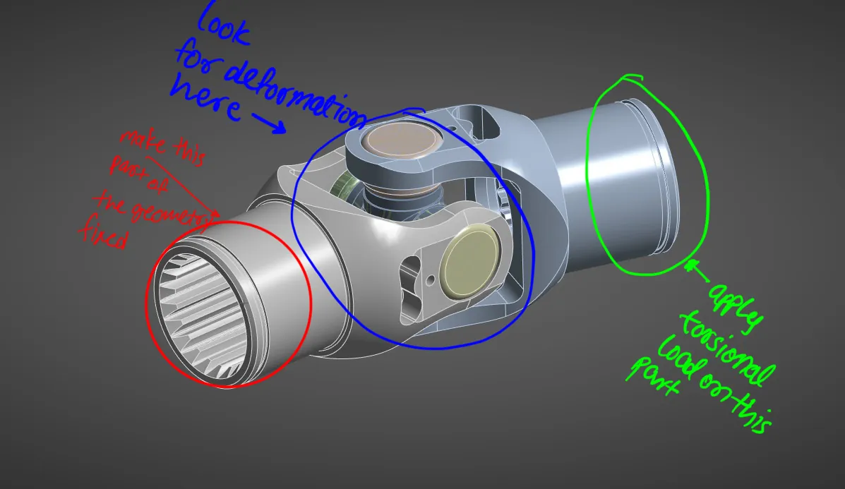
Before any of that gets built, I set up my own Ansys Workbench model of the yoke and spider assembly in torsion to predict where it yields. The markup below is how I planned the load case: hold the splined end, twist the far end, and watch the ears.
Where it stands
Preliminary CAD is done and went through the team's first design review. Once the stand is built, its load and strain data will either back up the FEA or show us where the model is wrong.
Next project: Machining for SR26 and SR27 →